Step 5-Specify Field mappings for each Table/Feature Class
In this step, data source tables are mapped to the desired
modeling element types, and data source fields are mapped to the desired model
input properties. You will assign mappings for each Table/Feature Class that
appears in the list; Step 1 of the wizard can be used to exclude tables, if you
wish.
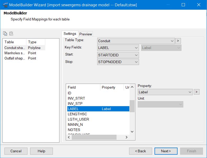
- Tables (list)-This pane, located along the left side of the dialog box, lists the data source Tables/Feature Classes to be used in the ModelBuilder process. Select an item in the list to specify the settings for that item. The tables list can be resized using the splitter bar.
- There are two toolbar buttons located directly above Tables list (these buttons can be a great time saver when setting up multiple mappings with similar settings).
- Settings Tab-The Settings tab allows you to specify mappings for the selected item in the Tables list.
- The top section of the Settings tab allows you to specify the common data mappings:
- Element Types-This category of Table Type includes geometric elements represented in the drawing view.
- Components-This category of Table Type includes the supporting data items in your model that are potentially shared among elements such as patterns, pump definitions, and controls.
- Collections-This category of Table Type includes table types that are typically lists of 2-columned data. For instance, if one table in your connection consists of a list of (Time From Start, Multiplier) pairs, use a Pattern collection table type selection.
- Key Field (Data Source) (drop-down list)-Choose the field in your data source that contains the unique identifier for each record. If you plan to maintain synchronizations between your model and GIS, it is best to define a unique identifier in your data source for this purpose. Using an identifier that is unique across all tables is critical if you wish to maintain explicit pipe start/stop connectivity identifiers in your GIS.
- When working with ArcGIS data sources, OBJECTID is not a good choice for Key field (because OBJECTID is only unique for a particular Feature Class). For one-time model builds -- if you do not have a field that can be used to uniquely identify each element -- you may use the <label> field (which is automatically generated by ModelBuilder for this purpose).
- Key Field (Model) (drop-down-list) - This field is only enabled if you specified <custom> in the "Specify key field to be used in object mapping?" option in the previous step. If you specified "GIS-IDs' or "Label" the field will be disabled.
- If you specified <custom>, then you will be presented with a list of the available text fields for that element type. Choose a field that represents the unique alphanumeric identifier for each element in your model. You can define a text User Data Extensions property for use as your <custom> model key field.
- The <custom> key field list is limited to read-write text fields. This is because during import, the value of this field will be assigned as new elements in your model are created. Therefore, the models internal (read-only) element ID field cannot be used for this purpose.
- Start/Stop - Select the fields in a pipe table that contain the identifier of the start and stop nodes. Specify <none> if you are using the spatial connectivity support in ModelBuilder (or if you want to keep connectivity unchanged on update). For more information, see Specifying Network Connectivity in ModelBuilder. When working with an ArcGIS Geometric Network data source, these fields will be set to <auto> (indicating that ModelBuilder will automatically determine connectivity from the geometric network).
- X/Y Field - These fields are used to specify the node X and Y coordinate data. This field only applies to point table types. The Coordinate Unit setting in Step 2 of the wizard allows you to specify the units associated with these fields.
- When working with ArcGIS Geodatabase, shape file and CAD data sources, these fields will be set to <auto> (indicating that ModelBuilder will automatically determine node geometry from the data source).
- Suction Element (drop-down list)-For tables that define pump data, select a pipe label or other unique identifier to set the suction element of the Pump.
- Downstream Edge (drop-down list)-For tables that define pump or valve data, select a pipe label or other unique identifier to set the direction of the pump or valve.
- Field - Field refers to a field in the selected data source. The Field list displays the associations between fields in the database to properties in the model.
- Property (drop-down list)-Property refers to a Bentley Drainage and Utilities property. Use the Property drop-down list to map the highlighted field to the desired property.
- Unit (drop-down list)-This field allows you to specify the units of the values in the database (no conversion on your part is required). This field only applies if the selected model property is unitized.
- Preview Tab-The Preview tab displays a tabular preview of the currently highlighted source data table when the Show Preview check box is checked.
To map a field in your table to a particular Bentley Drainage and Utilities property:
- In the Field list, select the data source field you would like to define a mapping for.
- In the Property drop-down list, select the desired Bentley Drainage and Utilities target model property.
- If the property is unitized, specify the unit of this field in your data source in the Unit drop-down list.
To remove the mapping for a particular field: